Description
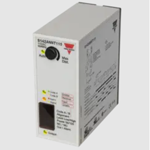
Amplifier for Through Beam sensors, Range up to: 50000mm, Adjustable Sensitivity, Diagnostic Functions, Alignment help, Power Supply : 230 Vac, NPN outputs, 11 pole Plug Connection, UL508, UL325, CSA.
Processor controlled amplifier for one set of photoelectric through-beam sensors, type MOF.., MMF.. and MNF (see separate datasheets for MMFTR15 and MOFT20). Utilizes an 11-pin circular plug for easy connection. 8 A SPDT relay output, NPN / PNP transistor output or alarm output. Diagnostics for sensor test during operation. Alignment help via LED or alternation of alarm output. Level indication for dirt accumulation. Manual or automatic emitter power regulation. Two emitter codes available for high neighbour immunity.
Specifications
Diagnostics If a fault occurs on either the emitter or receiver the Alarm LED and output will turn ON.
Receiver fault During normal operation the receiver is monitored for faults.
If the wires are short-circuited the “Code A, Yellow LED” flashes at a rate of 2 Hz.
If the wires are broken the “Code A, Yellow LED” flashes at a rate of 4 Hz.
Emitter fault During normal operation the emitter is monitored for faults.
If the wires are short-circuited the “Code B, Green LED” flashes at a rate of 2 Hz.
If the wires are broken the “Code B, Green LED” flashes at a rate of 4 Hz.
Alignment
If the alignment DIP switch is set the Yellow Signal LED Flashes according to the signal quality.
Low frequency means weak signal.
Steady indication means maximum signal. On long distance it is not possible to get a steady signal but the alignment is optimal when the led flashes with the highest frequency.
On short distance the sensitivity can be reduced using the potentiometer and then get better readings in the alignment LED.
The ALARM output will follow the Signal LED in alignment mode, so a Sensor tester (optional) can be connected to serve as a remote indication during alignment of the sensors. NB! In alignment mode the output is off.
Code A or B When two sensor pairs are mounted close to each other it is recommended to select one set to Code A and the other to Code B to minimize crosstalk.
Dirt reserve
For optimal detection excess gain settings can be selected using the Level Low/High DIP switch:
•High: Allows high dirt build-up.
•Low: Allows detection of semi-transparent objects.
Power settings
To avoid a too strong emitter the power can be reduced to 50% reducing the max distance to 25%


